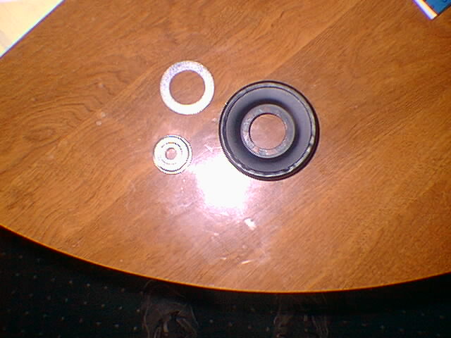
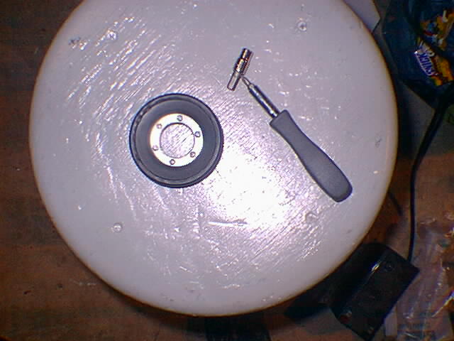
Here are the magic components. The bearing (lower left) fits perfectly the Weld-on pulley (right).
The precision washers fit both the bearing OD and the step in the pulley ID. Who'd a thunk it?
While the still make parts for this old veteran, they can be rather "spendy." I could have paid $170 for a 12 volt conversion kit. Instead, I bought an alternator from the junk yard in Doon, Iowa for $32. I'm repairing the original starter switch which was manual and has a transmission interlock so you can't start it in gear. This replaces the six volt solenoid that had been added. Of course the old starter didn't work - ya couldn't push the button in. I took it apart and found the innards rusted solid. A little time with a Dremel tool and some time on the lathe and the parts became usable. I then threaded the shaft so a nut would hold on the original "push button" rather than reweld it together. It works! Cost zero. I picked up a Ford mechanical high current starter switch to replace the probably burned up old one on sale at a local hardware store. Cost $2 but I will have to make a bracket. Of course the new alternator had a pulley for a serpentine belt. I looked everywhere for a replacement V-belt pulley that was wide enough for the 5L agricultural belt on the tractor. No luck. So, I made one (Pictures here). The alternator needs a smaller pulley than the old generator so it spins fast enough at the tractors low RPM. That, natcherally, makes the belt too long. Viola! An idler pulley is needed. Finding a 3 - 4 inch pulley with a 3/8" arbor that fits a 5L belt is like finding silk athletic sox. Someone probably makes them but you can't find them and if you DID find them you couldn't afford them. Once again down to the basement and the lathe.
The idler pulley is made from a weld-on pulley from the local agricultural store which just happens to have a center hole exactly the same size as the outer diameter as an inexpensive bearing from Ace Hardware. Combine those parts with a couple of precision washers having the same ID as the pulley and an OD that fits the step in the pulley and you get an idler pulley for a 1943 Ford N 12 Volt conversion!
Here are the magic components. The bearing (lower left) fits perfectly the Weld-on
pulley (right).
The precision washers fit both the bearing OD and the step in the pulley ID.
Who'd a thunk it?
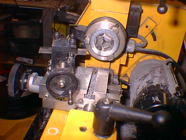
This picture shows using the lathe to index six evenly spaced marks and a perfectly
symetric ring.
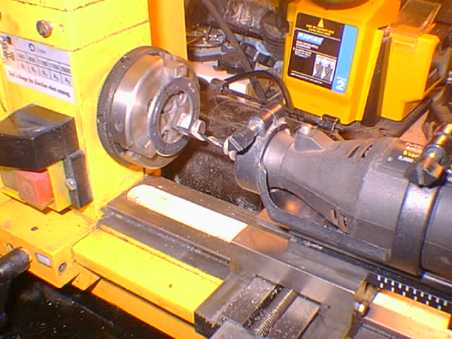
I adapted my Dremel tool to attach in place of the lathe's tool post. Now I
can drill holes precisely at the index marks.
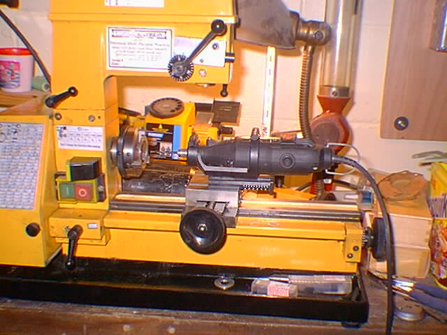
This is
another shot of the Dremel tool/ lathe setup.
Using the newly drilled precision washer as a template, I used the big drill
press to drill matching holes in another precision washer and in the Weld-on
pulley.
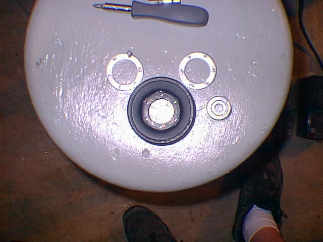
Here are all the parts after machining.
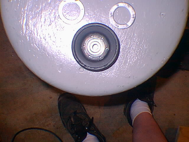
The bearing is inserted into the Weld-on pulley.
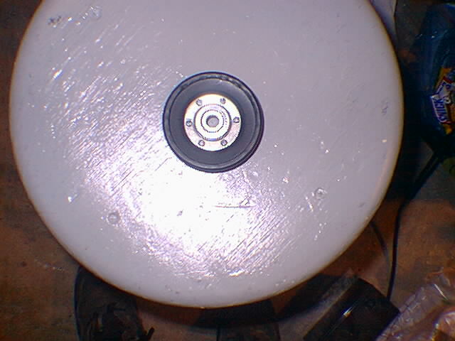
This is
the completed idler pulley. It uses six machine screws, lock washers, and nuts.
The nuts also use Locktite. There should be little vibration as the assembly
is inherently balanced.